top of page

Analysis
The analysis of the RC Baja consists of three engineering merits: mechanics of materials, mechanical design, and dynamics. Mechanics of materials involve in force and material analysis. Mechanical design involves in designing analysis, and dynamics involves motion analysis. The analysis shown below cover concepts such as gear ration, material thickness, and material selection to determine the optimum design of the RC Baja while meeting the requirements.
Requirements:
1. The vehicle must go at minimum speed of 10 mph.
2. The vehicle must go at maximum speed of 25 mph.
3. The vehicle must drive a slope of at least 45 degrees.
4. The chassis must carry a combined load of at least 5 lbs.
5. The chassis must withstand all the external and internal forces of 40 lbs. without failing or fracturing.
6. The chassis must be lightweight of 8 lbs.
7. The vehicle must keep its structure off a jump of one and a half feet.
8. The drivetrain and chassis are expected to have a life expectancy of five years.
9. Both the drivetrain and chassis are expected to line with the suspension and the steering components within 10 thousandth.
10. A size of 8 by 12 inches for easy steering and weight transfer.
11. A moderate cost of under $500 for building.
Analysis 1
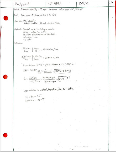
The first analysis is geared to calculating the gear ratio of the drivetrain using dynamics. The ratio is based on the maximum rpm of the motor and the rpm of the wheels and axle. The maximum rpm of the motor is 50,000 rpm and the rpm of the wheels is 2211.42 rpm; therefore, the gear ratio is 22:1. However this is higher compared to other gear ratios; therefore, a gear reduction of 10:1 is used, which a pinion gear of 12T and a spur gear of 120T will be used.

Analysis 2
The second analysis consists of calculating the input and output torque based on the motor. Using dynamics, the input torque is 1.521 lb.*in. and the output torque at the axle is 15.21 lb.*in. after multiplying the input torque by the gear ration of 10:1. The required torque to move the wheels is 15.2, therefore; this meets the requirement.
Analysis 3
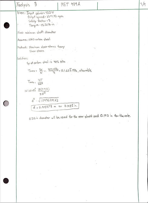
The third analysis determines the minimum diameter of the rear shaft or axle using mechanics of materials and the torque calculated in analysis two. The requirement is that the maximum shear stress does not exceed 485 MPa. Using a safety factor of three, the allowable shear stress is 161.66 MPa, which brings the minimum diameter of the rear shaft to be 0.1488 in. However, a quarter of an inch will be used for easy machining as shown in JCC-20-004.
Analysis 4
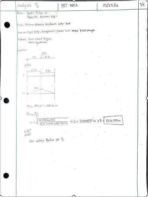
The fourth analysis determines the minimum thickness of the chassis plate for the vehicle with a selected material of 6061 Aluminum under a weight of 8 lbs. as shown in JCC-20-002. It is also assumed that the yield strength is 40 ksi. Therefore, with all the given, the minimum thickness of the chassis plate is 0.1209 with a safety factor of 3; however, an eighth of an inch will be used for this project.
Analysis 5
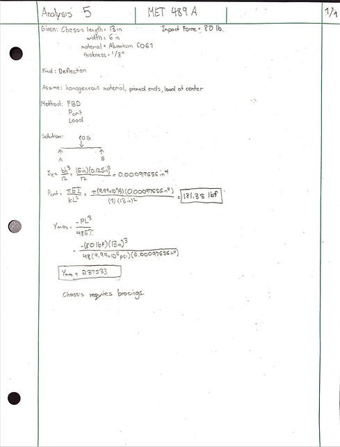
The fifth analysis determines whether the chassis requires bracings. Using mechanics of materials, the maximum deflection of the chassis (JCC-20-002) was determined using the max deflection equation of a beam with supported ends. The requirement is that the maximum deflection must not exceed 0.100 in. However, the maximum deflection of the chassis is 0.37533 inches; therefore, the chassis needs bracings.

Analysis 6
The sixth analysis determines the maximum speed of the vehicle. The requirement is that the vehicle must reach a speed of 25 mph. Using dynamics, the gear ratio is 10:1, which brings the speed at the axle to 5000 rpm. After conversion, the maximum speed of the vehicle is 56.52 mph, which meets the requirement.
Analysis 7
The seventh analysis determines the belt length depending on the gears used, which in this case have two identical gears with a pitch diameter of 3.056 in. The requirement is that the velocity ratio must be 10; therefore, 120 teeth is used as the spur gear with a pinion gear of 12 teeth. The Belt perimeter length is calculated to be 21.6 in.


Analysis 8
The eighth analysis determines the maximum deflection of the rear axle (JCC-20-004) that will have an impact force of 80 lbs. The requirement is that the deflection must not exceed 0.100 in. Using mechanics of materials, specifically the beam deflection equation, the maximum deflection of the rear axle came out to be 0.0001703 in. Therefore, does not require additional supports.
Analysis 9
The ninth analysis determines the design v belt for the RC Baja drivetrain. The requirement is that the belt must fit with the right dimensions such as width and length into the XL pulley as seen in appendix B08 and B09. Using the design power equation, the design power came out to be 1.45 hp, using a service factor of 1.2. The velocity ratio equation determined the ratio between two pulleys, which is 1:1. Belt size was assumed, while drive size was calculated to be 1.681 in after using the drive size equation. Using the center distance equation, the distance between two pulleys came out to be 5 in. This information helps with calculating the Length of the belt, which is 13.14 in, but 13 in will be used as standard.

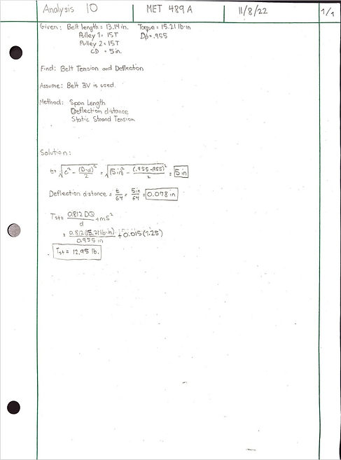
Analysis 10
The tenth analysis determines the tension and deflection of the belt between two pulleys. The requirement for this analysis is that the tension must not be greater than 20 lb. Assuming the 3V belt is used shown in appendix B09, the length between two pulleys is 5 in., using the span length distance. Therefore, the deflection can be calculated by dividing the span length by 64. The deflection is 0.078 in. Lastly, using static tension equation, the tension of the belt is 12.95 lb., which is less than 20 lb.; therefore, this analysis meets the requirement. The calculations can be found in appendix A10.
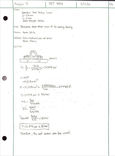
Analysis 11
The second to the last analysis determines the shear stress of the set screw (JCC-50-001) that will be used to hold the bearing housings in placed with the chassis. And the requirement is that the shear stress must not exceed the yield strength of the material which is 30 ksi. Using mechanics of materials to do a shear stress analysis, the shear stress calculated is 25.873 psi after dividing the force by area. Since 25.873 psi is less than 30 ksi; therefore, the set screw is more than efficient as a fastener for the bearing housings. In addition, a safety factor of 3.0 was used to calculate the allowable stress, which is 10 ksi, which is more than 25.873 psi.

Analysis 12
The last analysis determines the bending stress of the pinion and spur gears. The requirement is that the pinion bending stress must be less than 13778.85 psi and the gear bending stress must be less than 415 MPa. This analysis is a mechanics of materials and bending stress analysis. After using the bending stress equations with the required values such as tangential force, J and size factor, and load-distribution factor, the calculated bending stress of the pinion and spur gear is 1158.88 psi and 631.25 psi, which is a lot lower than the yield strength of brass and 303 stainless-steel. Therefore, the pinion gear and the spur gear will not bend when in contact with each other.
bottom of page